During its service life a fatigue loaded structure undergoes a large number of different load cycles. The load spectrum describes the frequency of different variations in the stress range during different load cycles. The maximum stress range, the total number of load cycles and the load spectrum are the primary load parameters. A longer service life is obtained when there are a lot of small stress range cycles and only a few of the maximum value. Thin load spectra cause less damage than full load spectra.
It is very important to avoid abrupt changes in stiffness and to try to minimize stress concentrations. However, it is not possible to design a structure without local stress raisers. Then the reference fatigue tests are helpful to quantify the change in life for different solutions.
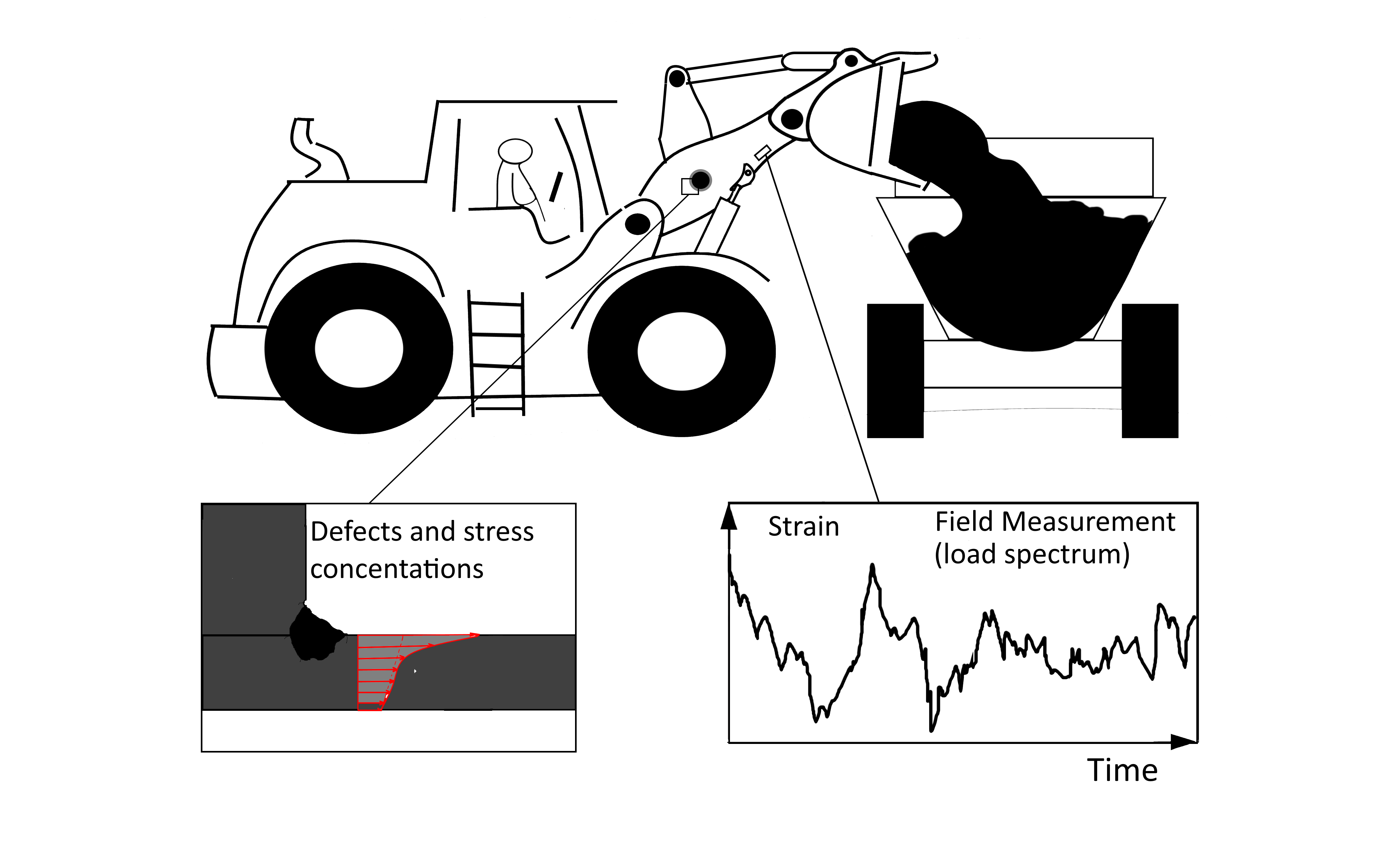
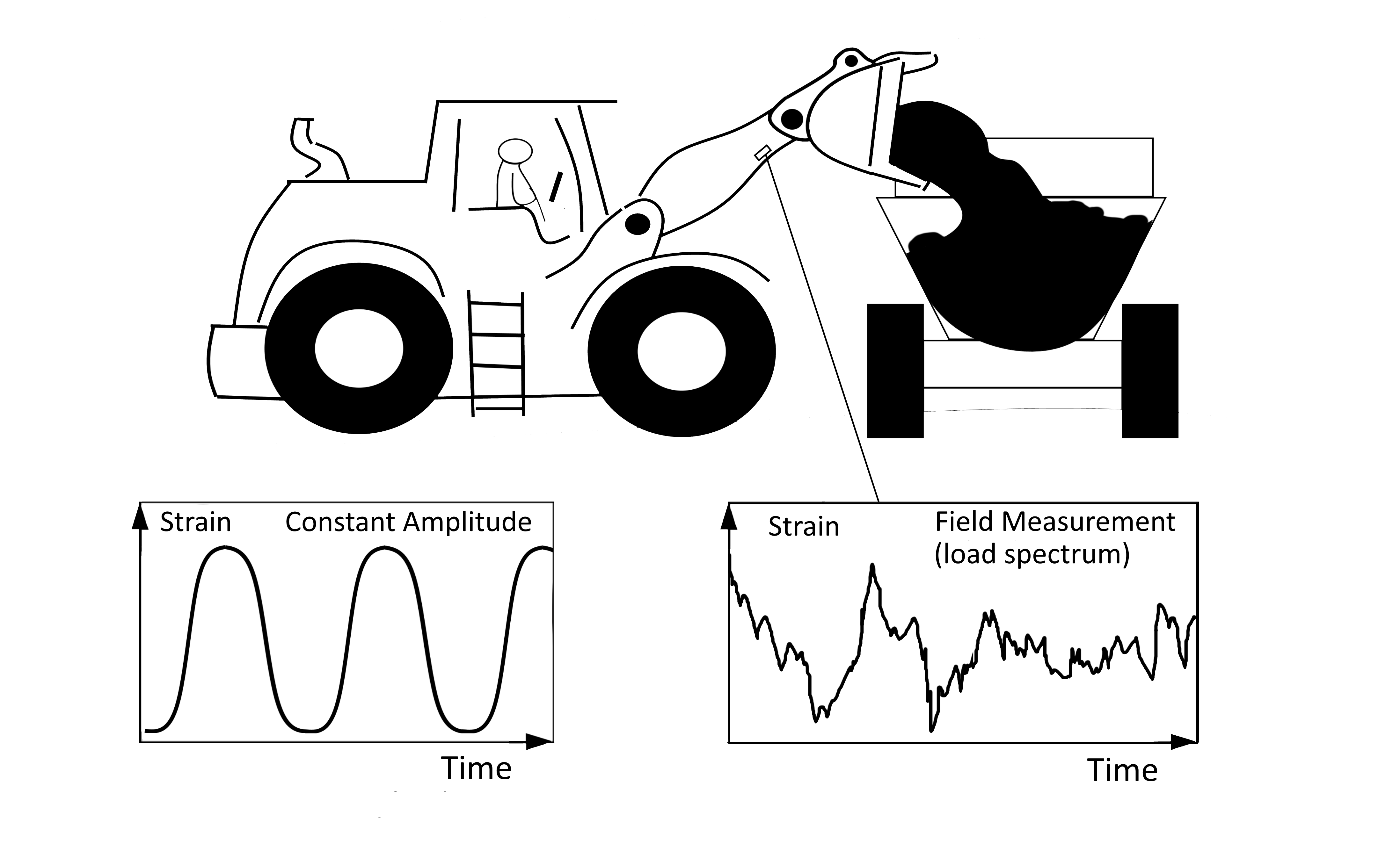
Picture 1: Load history, stress concentrations and local geometry are primary fatigue design parameters. The fatigue life is very dependent on local effects, e.g. defects and stress concentrations.
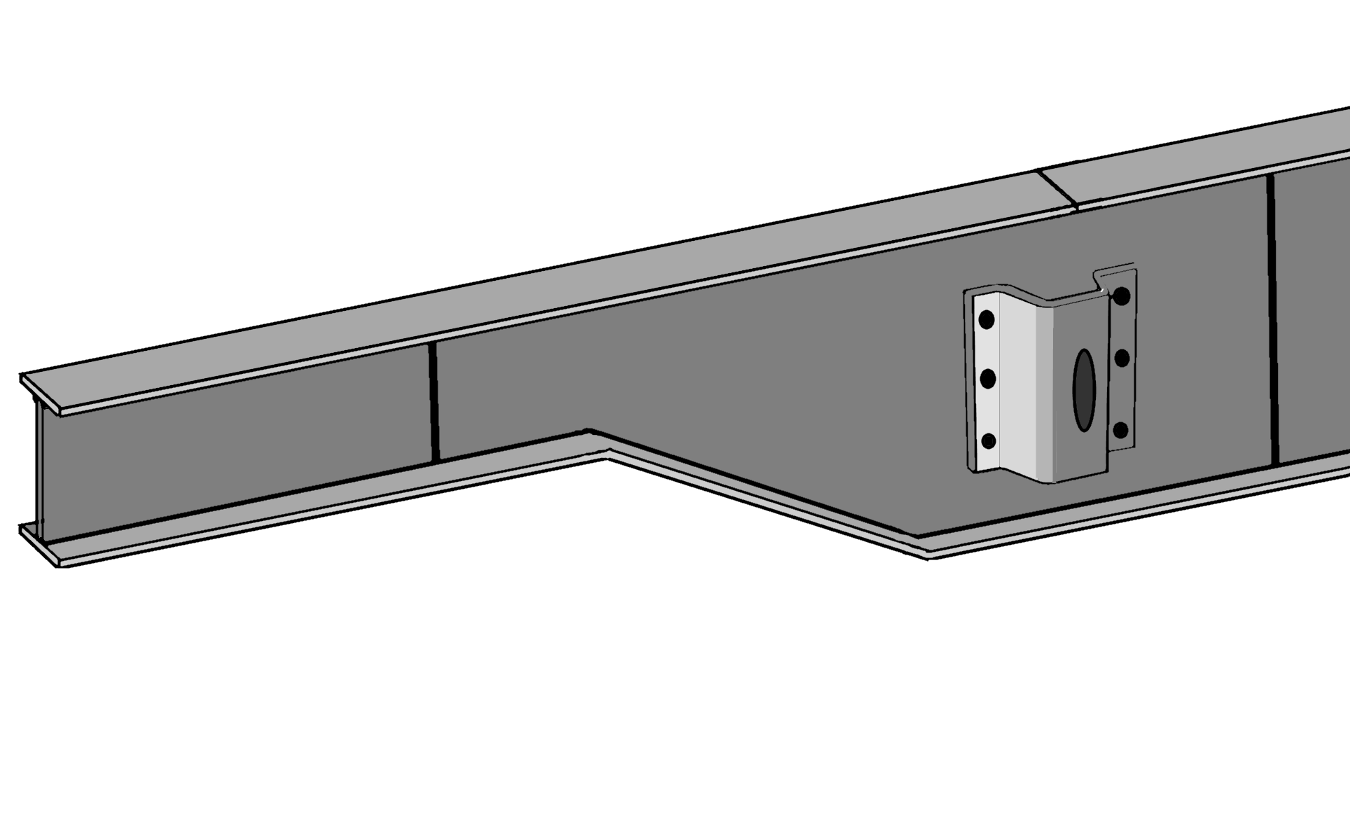
Design of load attachment details is important. Unfortunately, the load attachments need often to be placed in the regions where the nominal stresses are high. Welding the load attachment to the structure can then lower the fatigue strength. However, by good design this can be handled and there are many design guidelines, picture 2.
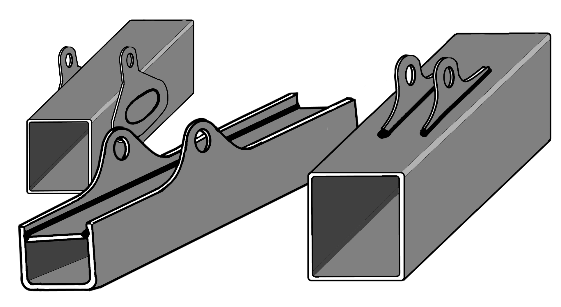
Picture 2: Typical load attachements in a fatigue loaded design.
When designing beams and main components to fatigue loaded structures try to make all transitions of geometry as smooth as possible. Avoid accumulation of weld joints and other stress raisers as far as possible. Picture 3-4.
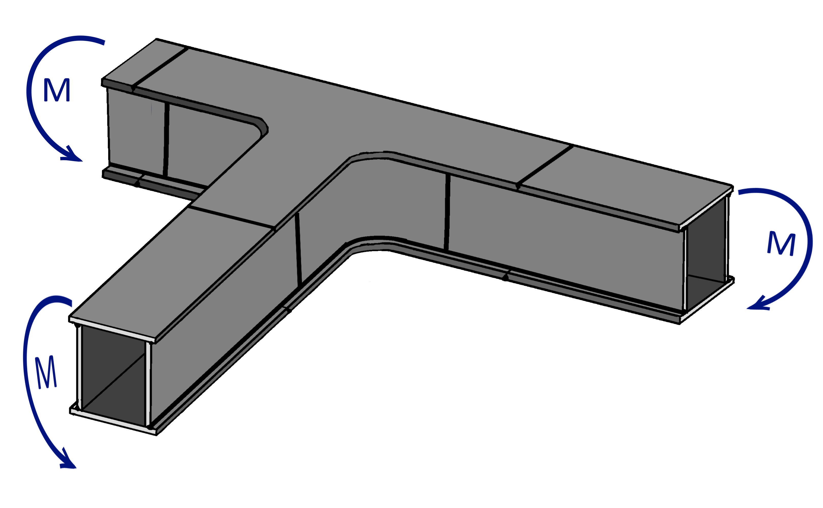
Picture 3: Beam with smooth transitions and as few overlapping welds as possible.
Picture 4: Smooth transition of height and welds apart.
The stiffness of the structure decides how it responds to a dynamic load. A stiff structure with a lot of stiffeners is only suited for static load. When a dynamic load, e.g. a fatigue load or an impact load, is applied a flexible structure allows larger deformation and often subsequently lower stresses than a stiff structure. A flexible structure with well-balanced stiffeners is recommendable for fatigue load. The fatigue strength is very dependent on the local geometry.
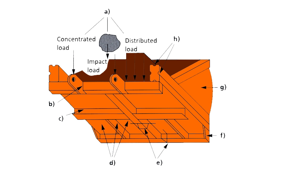
Picture 5: Stiffeners
a) The load is crucial for the design of stiffeners.
b) Stiffeners at loadings.
C) Stiffeners reduce the width of the free flat sheet and restrain local deformation. Thereby local buckling is prevented.
d) In flat sheet areas, stiffeners may be inserted to raise the local load capacity.
e) Stiffeners work together with the plate (effective width) as a beam.
f) Stiffeners can increase the torsional stiffness by preventing warping of the cross section.
g) Sometimes it may be better to use a curved sheets instead of a flat sheet, due to membrane stresses and skin action.
h) Stiffeners (e.g. grooves and edge folds in webs and flanges) raise the total load capacity of the cross section.