In this example, we have a bracket in a fatigue loaded structure, picture 1. It is loaded by a dynamic load and the number of cycles during the brackets life is 800 000, the spectrum is described with a spectrum factor of 0.1. Note that it is NOT a full spectrum.
The bracket has a hole in the flange at one location and a T-joint in an area with lower nominal stress. The maximum stress range in the flange base material is 350 MPa, close to the hole the stress range is 300 MPa and close to the weld 200 MPa. Note that we are using the nominal stress range at the three different locations.
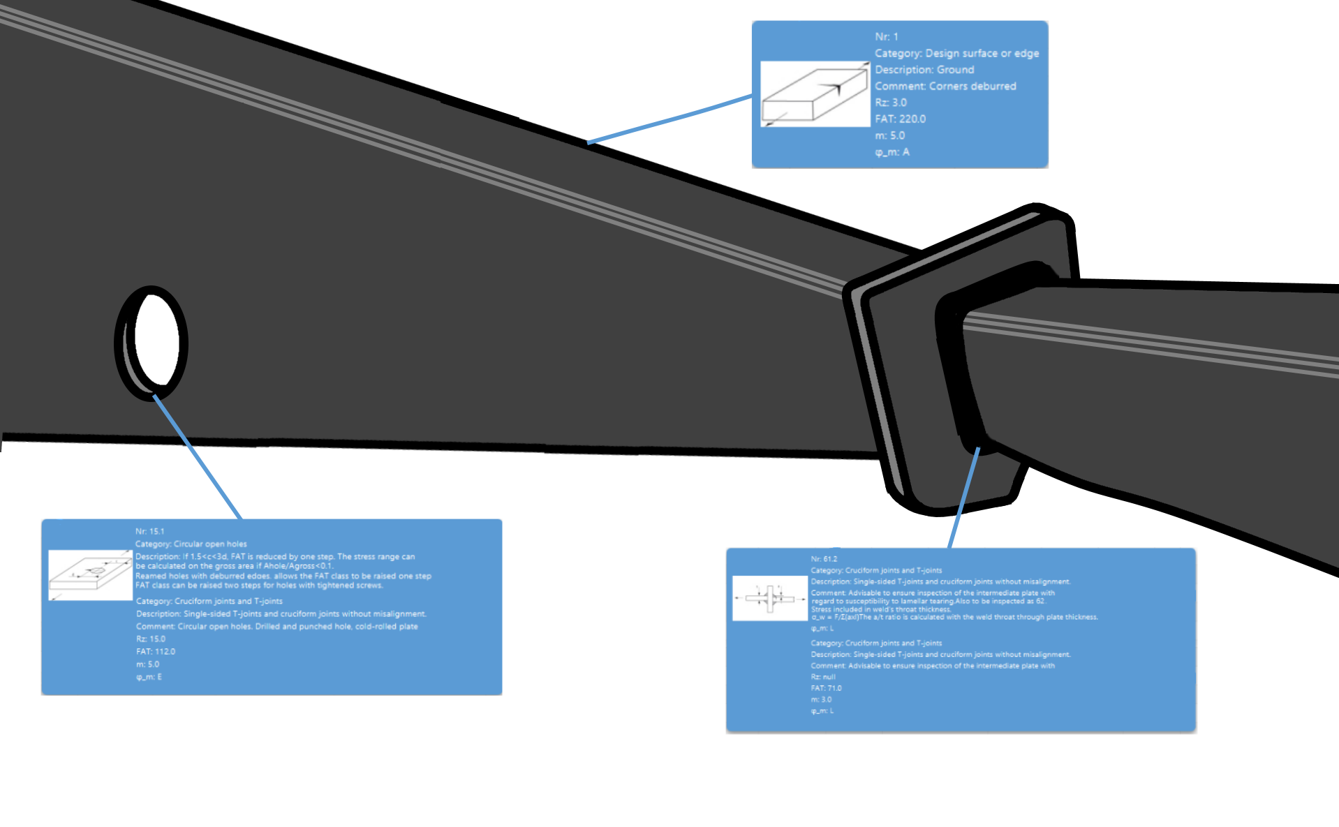
Picture 1: Bracket.
We now need to check the fatigue design criteria at these three locations: The flange (actually the edge of the flange), the hole and the weld joint. We have done three design computations using the same Design Calculation Sheet. Then we can save them all in one file. It is also possible to show the calculations and the sheet and compare them, as we do in picture 2. Note that we have the same ranges of the diagram in all pictures when we compare the graphics of the SN-curves-
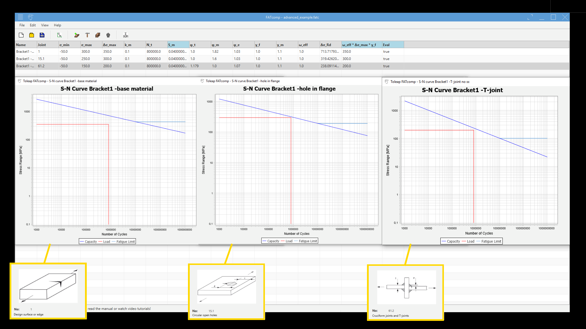

Picture 2: The Calculation Sheet and the SN-curves for the critical points in the bracket.
Good Luck with your fatigue design!